| English / Deutsch | Print version |
RC Viewer, RC Gamepad, Play video games with the RC Transmitter as Game Controller
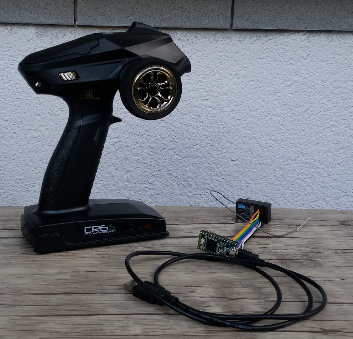
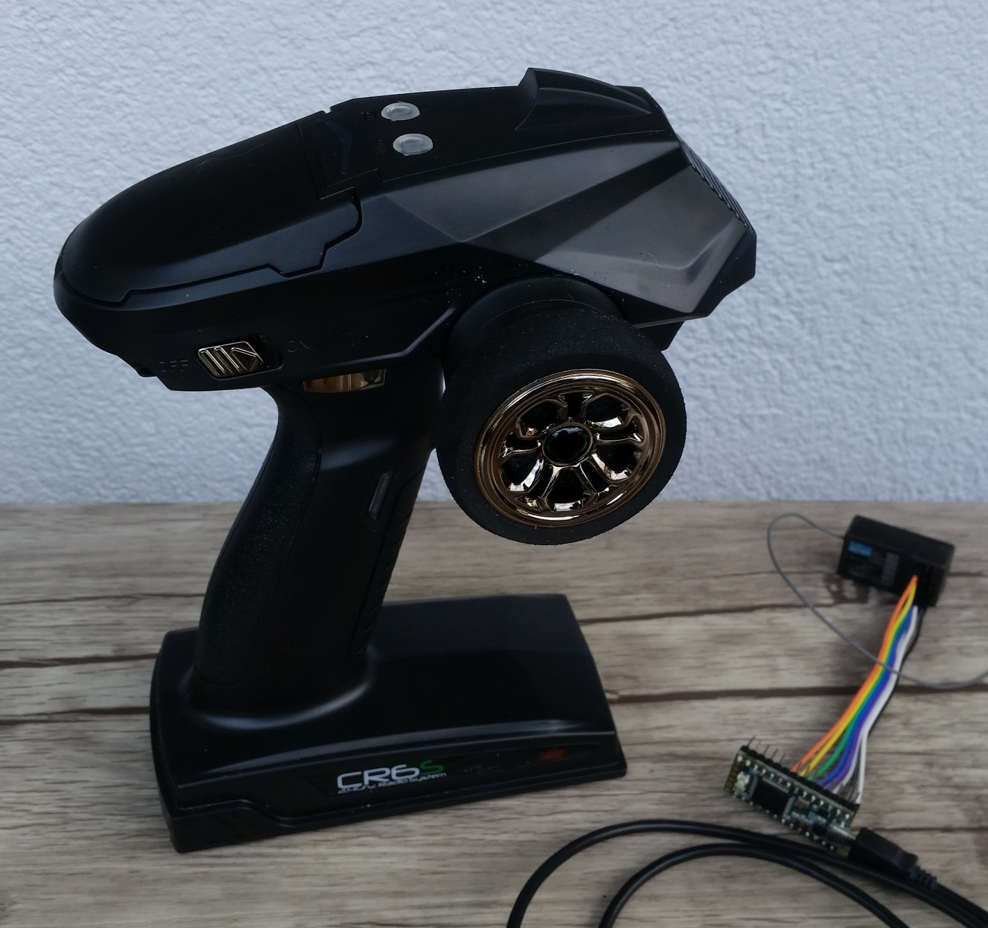
I like RC (radio controlled) vehicles and thought it would be great to play racing games with the RC Transmitter. I checked the internet and as always, someone else had already that idea. One solution is using the Andurino and another is using Flightsim. I decided to use my own solution. I am using a Teensy 3, some wires and a 6 channel RC Transmitter/Receiver.
It is also a great solution for handicapped people to play racing games.
I released two programs:
- RC Viewer, shows the impulse lengths.
- RC Gamepad, a USB Gamepad with different modes and features.
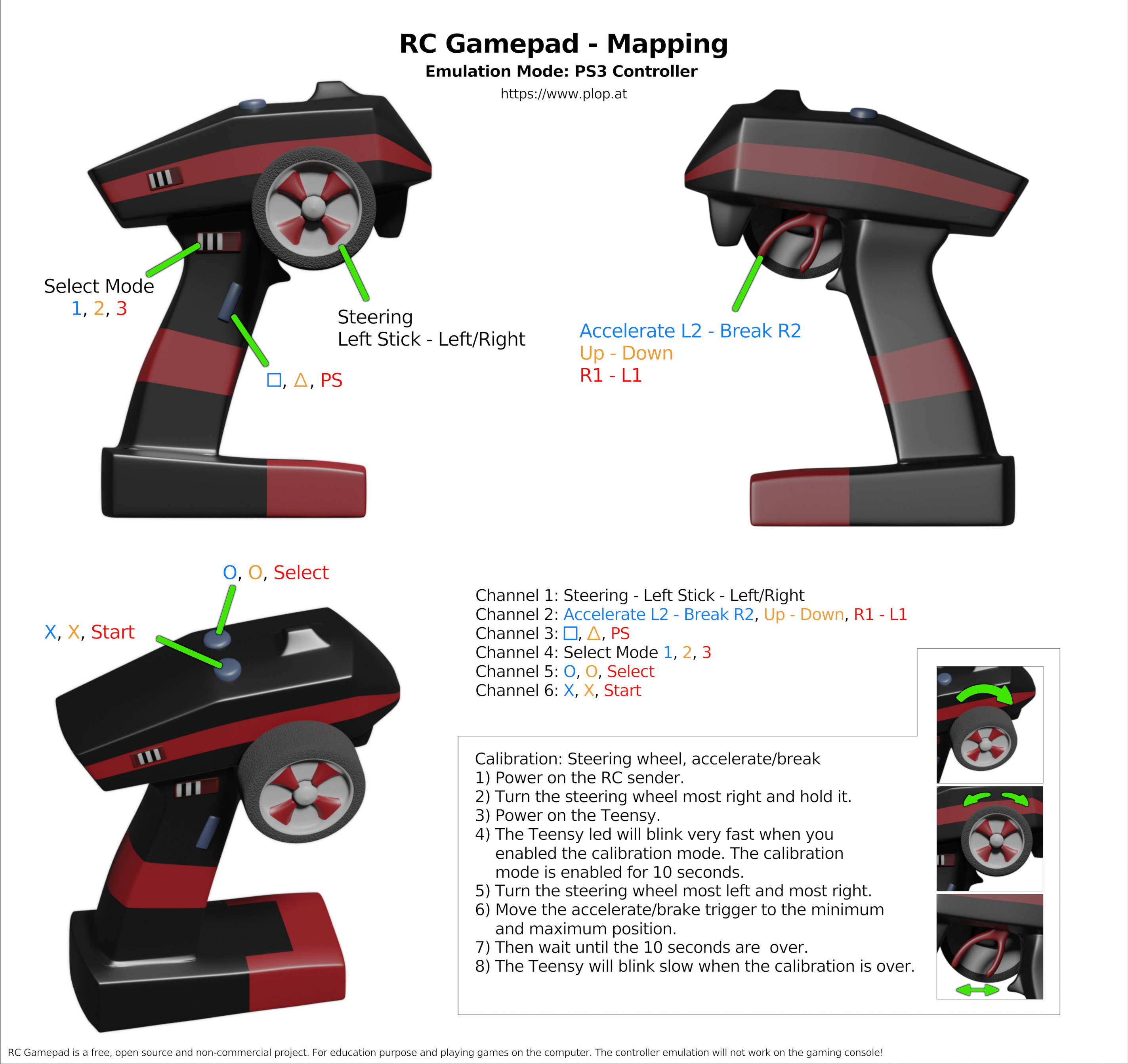
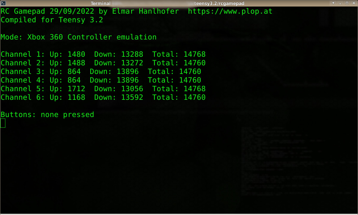
The RC Gamepad can be used as gamepad and it can emulate a Xbox 360 Controller and a PlayStation 3 Controller (see description for limitations).
Hardware
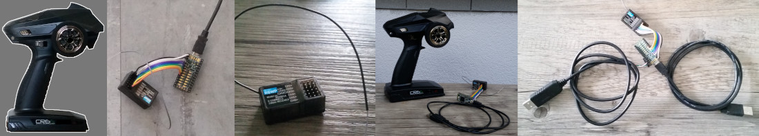
- Teensy 3.2 with pins soldered
- Absima CR6S RC Transmitter Receiver 2.4Ghz 6 Channel
- USB cable - USB 2.0 Cable A to Micro M/M
- Jumper Wires 10cm
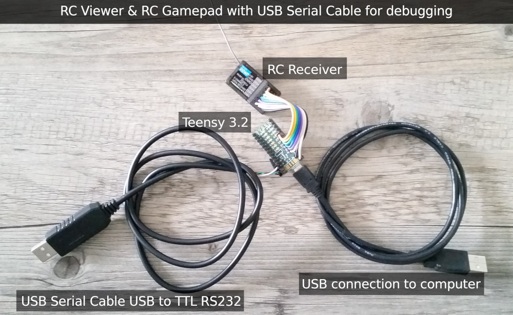
- USB Serial Cable COM-FOUR PL2303HX USB to TTL RS232 COM for debugging
Source codes
RC Viewer: rcviewer-20220821.zip, License: MIT
RC Gamepad: rcgamepad-20221004.zip, License: GPLv2
Videos
External content blocked. Watch on YouTube
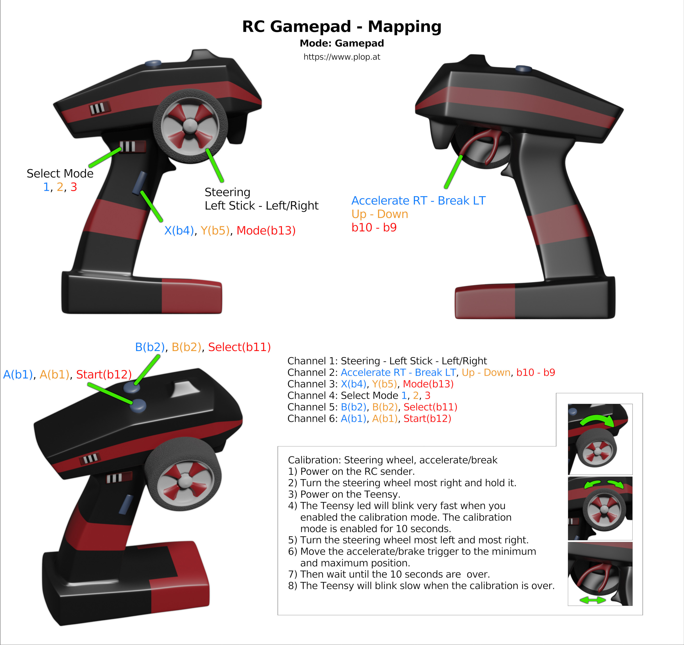
RC Gamepad/Controller mapping

Mode information
Various blink modes when transmitter is not powered on startup and for mode 1 - 'gaming mode', mode 2 - 'menu mode', mode 3 - 'alternate buttons mode'.
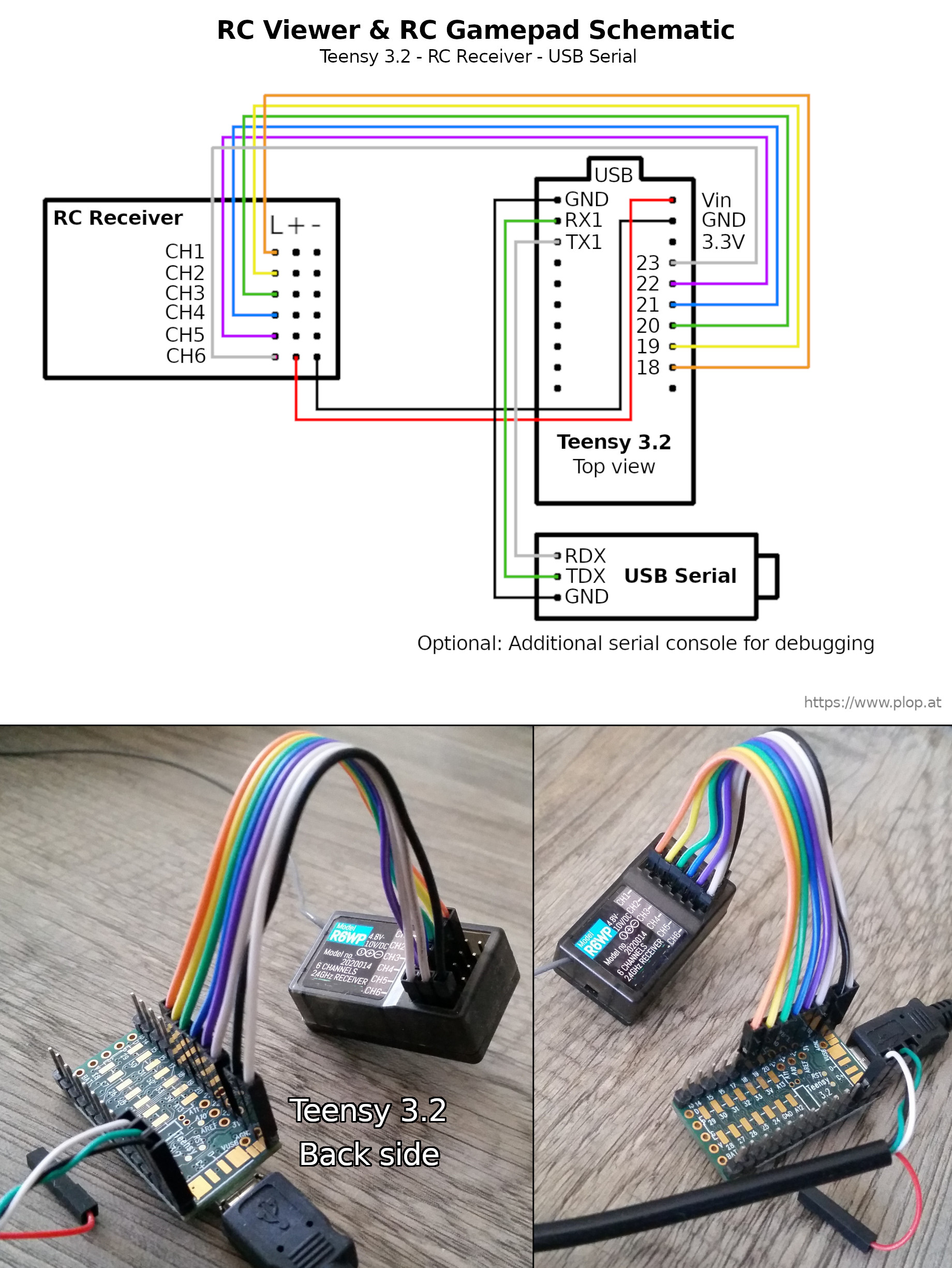
How it works, circuit diagram
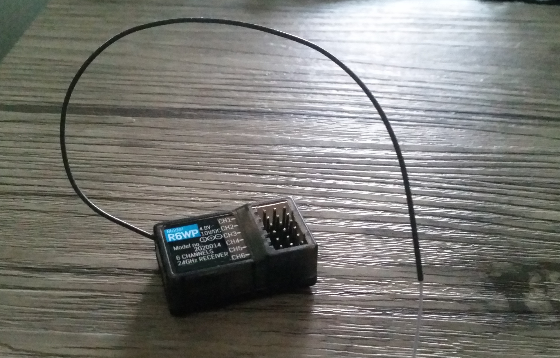
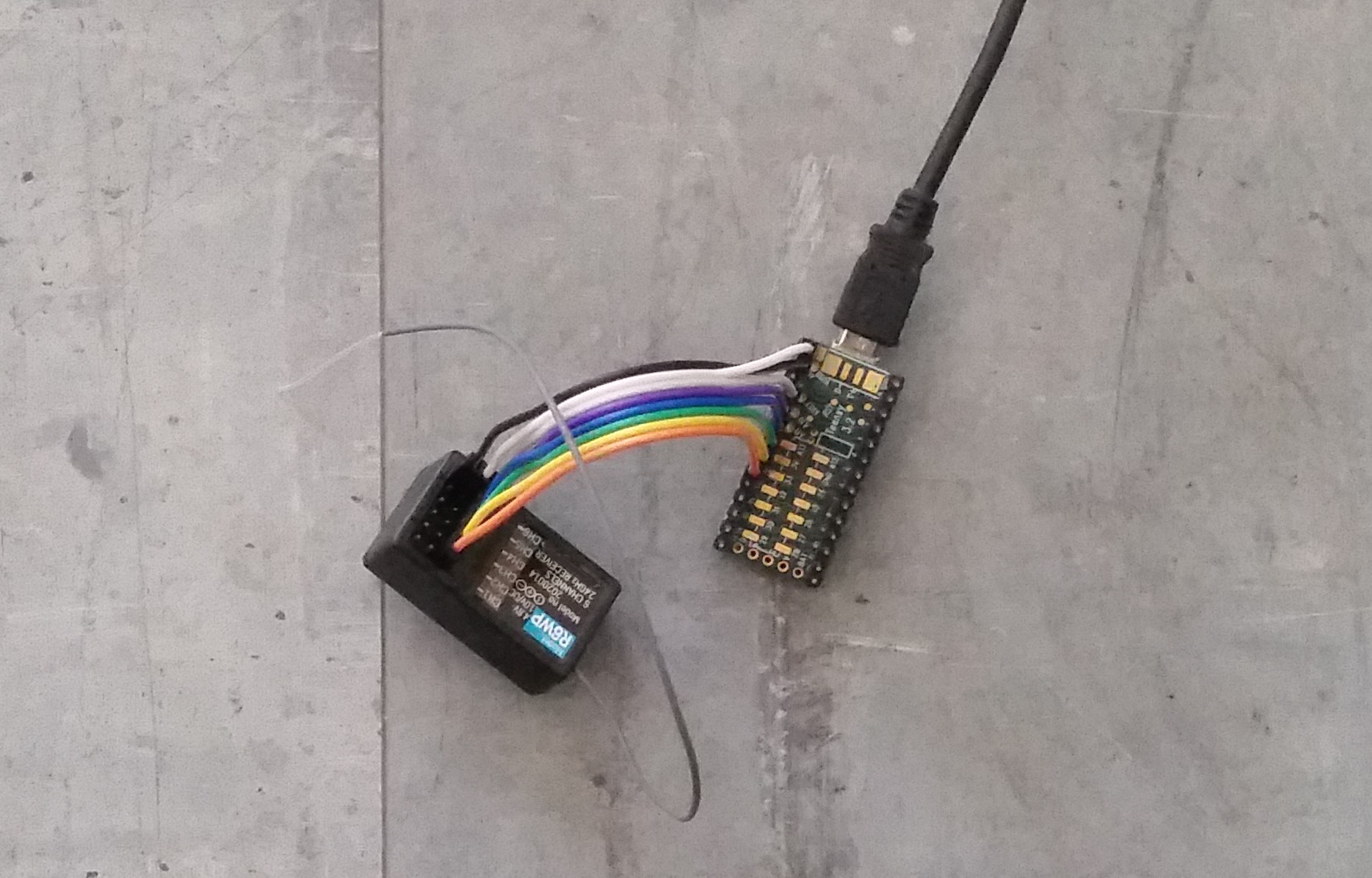
The RC Receiver gives continuous pulses as output. The impulse length is between a minimum and a maximum length. The length of the pulse is corresponding with the angle of the servo or the speed of the motor. Every channel has its own pulse output. I read the output of the RC Receiver with the Teensy using the digital input pins and interrupts on state change. The RC Receiver can work with 4,8V-12V and is powered by the 5V of the Teensy USB connection.
Output from the Teensy as Serial USB device (program RC Viewer) and minicom
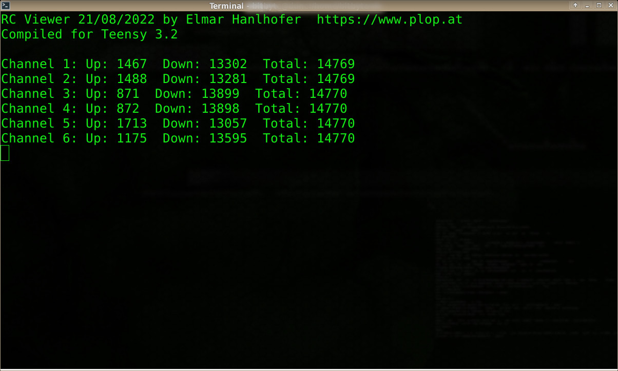
Channel example
Channel 1, controlled by the steering wheel of the RC Transmitter.
Note, your receiver may have different pulse rates. My receiver starts around every 14700µs a pulse. The minimum length of a pulse is about 936µs, the maximum is about 2000µs.
- Steering wheel in neutral position: Impulse length about 1480µs.
- Turning the steering wheel left: According to the angle between 963µs and 1480µs.
- Turning the steering wheel maximum left: Impulse length about 936µs.
- Turning the steering wheel right: According to the angle between 1480µs and 2000µs.
- Turning the steering wheel maximum right: Impulse length about 2000µs.
Pulse diagram
These values are from my receiver. You can get the values of your hardware with RC Viewer.

RC Viewer
1. The program RC Viewer
The program prints the impulse lengths from a RC receiver to a serial terminal. The serial output can come directly from the Teensy as USB Serial device or with the Teensy serial pins. You can use for example the program 'minicom' to see the output.
License: MIT, see LICENSE.txt
Download: rcviewer-20220821.zip
2. Hardware
- Teensy 3.2 with pins soldered
- Absima CR6S RC Transmitter Receiver 2.4Ghz 6 Channel
- USB cable - USB 2.0 Cable A to Micro M/M
- Jumper Wires 10cm
- (Optional) USB Serial Cable COM-FOUR PL2303HX USB to TTL RS232 COM for debugging
3. Program details
Main program: rcviewer.cpp
3.1. Serial output
Setup in the section: Terminal connection
Teensy as USB Serial device: #define serial Serial
Teensy RS232 serial pins : #define serial Serial1
Output refresh rate in milli seconds: #define TERMINAL_REFRESH_MS 200
3.2. Output device nodes
Teensy as USB Serial device : /dev/ttyACM0
Teensy RS232 serial pins to USB: /dev/ttyUSB0
3.3. Examples with minicom
minicom -b 115200 -D /dev/ttyACM0 -o
minicom -b 115200 -D /dev/ttyUSB0 -o
Leaving minicom: Press CTRL-A, then 'q'.
See also the script 'minicom.sh'.
3.4. RC receiver
Setup in the section: Remote control
Define number of transmitter channels: #define RC_NUM_CHANNELS 6
You can keep '6' even when your transmitter has only two channels.
Setup the used Teensy pins wired with the RC receiver.
rc_interrupt_pin[RC_NUM_CHANNELS] = {18, 19, 20, 21, 22, 23};
3.5. Setup channel
Init channel 1, usual the steering wheel:
RC_InitChannel (1, Isr1);
Init channel 2, usual accelerate/break:
RC_InitChannel (2, Isr2);
Print channel 1 data:
RC_PrintChannel (1);
4. How to compile
4.1. Install compiler
Download and install the Arduino IDE
https://www.arduino.cc/en/software
Download Teensyduino and install to the Arduino IDE directory
https://www.pjrc.com/teensy/td_download.html
4.2. Setup the Makefile
Open the Makefile of RC Viewer and set
• the ARDUINO_HOME variable to your Arduino IDE installation directory.
• the M_ARDUINO_VERSION variable to your Arduino IDE version.
• the M_TEENSYDUINO_VERSION variable to your Teensyduino version.
• the M_TEENSY_VERSION variable if you use another 3.x Teensy than the 3.2.
4.3. Compile
Run 'make' to compile the program.
You find the compiled program (rcviewer.hex) in the 'bin' directory.
5. How to flash
5.1. Tool
Use the program 'teensy_loader_cli' to flash the Teensy.
Download: https://www.pjrc.com/teensy/loader_cli.html
5.2. Command to flash
Press the white button on the Teensy to switch to the flash mode.
Run: teensy_loader_cli -mmcu=mk20dx256 -v -w bin/rcviewer.hex
You can also use the 'flash' script: ./flash
RC Gamepad - Game Controller
1. The program RC Gamepad
RC Gamepad allows you to play video games with a RC (radio controlled) transmitter and receiver. RC Gamepad can work as simple USB Gamepad, emulate a Xbox 360 Controller or a PlayStation 3 Controller. The emulated console controllers will NOT work on their consoles, because the required security mechanism is not implemented. The USB descriptors are not shipped with this source code. You can get the USB descriptors with the tool 'getdescriptors' when you own the original controller. See '9. Console controllers' for more information.
License: GPLv2, see LICENSE.txt
Download: rcgamepad-20221004.zip
2. Hardware
- Teensy 3.2 with pins soldered
- Absima CR6S RC Transmitter Receiver 2.4Ghz 6 Channel
- USB cable - USB 2.0 Cable A to Micro M/M
- Jumper Wires 10cm
- (Optional) USB Serial Cable COM-FOUR PL2303HX USB to TTL RS232 COM for debugging
3. Program details
Main program: rcgamepad.cpp
3.1. Controller type
Set the CONTROLLER_TYPE variable. Possible values are
 CONTROLLER_GAMEPAD
 CONTROLLER_XBOX360
 CONTROLLER_PS3
Example:
#define CONTROLLER_TYPE CONTROLLER_GAMEPAD
See '9. Console controllers' for details.
3.2. Debug output
Debugging is optional. Use an USB to RS232 device to connect to a serial terminal.
Set the DEBUG_TYPE variable. Possible values are DEBUG_NONE, DEBUG_USB_CONFIGURE, DEBUG_USB_IN_REPORT, DEBUG_USB_OUT_REPORT, DEBUG_USB_DATA, DEBUG_USB_VERBOSE
The DEBUG_TYPE variable is a bitmask. Use the logical or for multiple options.
Examples:
#define DEBUG_TYPE DEBUG_NONE
#define DEBUG_TYPE (DEBUG_USB_CONFIGURE | DEBUG_USB_OUT_REPORT)
#define DEBUG_TYPE DEBUG_USB_VERBOSE
3.3. Print RC values
You can print the RC values to a serial terminal. Enable
#define PRINT_RC_VALUES
If PRINT_RC_VALUES is enabled, then the screen will be shown automatically. If PRINT_RC_VALUES is not enabled, then the screen can be enabled on demand by pressing the key 'v'.
Note: If you also enable USB debugging, then the serial terminal screen will be mixed with different data.
3.4. Channel numbers on RC Receiver
If your transmitter and receiver is using different channel numbers, then change the numbers:
#define CHANNEL1 1
#define CHANNEL2 2
#define CHANNEL3 3
#define CHANNEL4 4
#define CHANNEL5 5
#define CHANNEL6 6
3.5. Calibration or not
RC Gamepad has a calibration for the steering wheel and accelerate/brake trigger implemented. See 'Calibration' for information how to calibrate. The calibration result will be stored on the EEPROM of the Teensy. As alternative to the calibration, it is possible to use hardcoded values. You get the correct values for the channels with 'Print RC values'.
Calibration is enabled by default. To use hardcoded values remove or comment out
#define USE_CALIBRATE
Here are some hardcoded values from my RC Transmitter/Receiver:
// Steering wheel
#define CHANNEL1_MIN      936
#define CHANNEL1_RELAXED 1479
#define CHANNEL1_MAX     1999

// Accelerate/Break
#define CHANNEL2_MIN     1013
#define CHANNEL2_RELAXED 1475
#define CHANNEL2_MAX     1987

// Tristate channel
#define CHANNEL4_MODE1 1000
#define CHANNEL4_MODE2 2000

// Twostate channels
#define CHANNEL3_TIPPING 1200
#define CHANNEL5_TIPPING 1800
#define CHANNEL6_TIPPING 990
3.6. Button press time
Buttons are handled in a special way. See 'RC Buttons'. Set the variable BUTTON_PRESS_TIME press time. The time is in milli seconds.
#define BUTTON_PRESS_TIME 400
3.7. Buttons special feature
Buttons are handled in a special way. See 'RC Buttons'. The special feature hold buttons pressed until the accelerate trigger get below start position and also when a maximum press time has been reached.
#define FEATURE_KEEP_PRESSED
3.8. Terminal connection
You can use a serial terminal to print debug information and the values of the RC Transmitter.
#define SERIAL_PORT Serial1      // RS232 serial pins RX1 and TX1.
#define TERMINAL_REFRESH_MS 500  // Refresh rate for the terminal output. 500ms.
3.9. RC Receiver
Setup in the section: Remote control
Define number of transmitter channels: #define RC_NUM_CHANNELS 6
You can keep '6' even when your transmitter has only two channels.
Setup the used Teensy pins wired with the RC Receiver.
rc_interrupt_pin[RC_NUM_CHANNELS] = {18, 19, 20, 21, 22, 23};
4. Serial terminal
You can use the hardware serial of your Teensy to connect to a serial terminal.
I am using a USB Serial Cable COM-FOUR PL2303HX USB to TTL RS232 COM. Connect
RDX to TX1, TDX to RX1 and GND to GND.
See the circuit diagram.
Output device node: /dev/ttyUSB0
As serial terminal use for example minicom.
minicom -b 115200 -D /dev/ttyUSB0 -o
Leaving minicom: Press CTRL-A, then 'q'.
See also the script 'minicom.sh'.
5. How to compile
5.1. Install compiler
Download and install the Arduino IDE
https://www.arduino.cc/en/software
Download Teensyduino and install to the Arduino IDE directory
https://www.pjrc.com/teensy/td_download.html
5.2. Setup the Makefile
Open the Makefile of RC Gamepad and set
• the ARDUINO_HOME variable to your Arduino IDE installation directory.
• the M_ARDUINO_VERSION variable to your Arduino IDE version.
• the M_TEENSYDUINO_VERSION variable to your Teensyduino version.
• the M_TEENSY_VERSION variable if you use another 3.x Teensy than the 3.2.
5.3. Compile
Run 'make' to compile the program.
You find the compiled program (rcgamepad.hex) in the 'bin' directory.
6. How to flash
6.1. Tool
Use the program 'teensy_loader_cli' to flash the Teensy.
Download: https://www.pjrc.com/teensy/loader_cli.html
6.2. Command to flash
Press the white button on the Teensy to switch to the flash mode.
Run: teensy_loader_cli -mmcu=mk20dx256 -v -w bin/rcgamepad.hex
You can also use the 'flash' script: ./flash
7. Calibration
You can calibrate the steering wheel and the accelerate/brake trigger.
1) Power on the RC Transmitter.
2) Turn the steering wheel most right and hold it.
3) Power on the Teensy.
4) The Teensy led will blink very fast when you enabled the calibration mode.
The calibration mode is enabled for 10 seconds.
5) Turn the steering wheel most left and most right.
6) Move the accelerate/brake trigger to the minimum and maximum position.
7) Then wait until the 10 seconds are over.
8) The Teensy led will blink slow when the calibration is over.
Instead of the calibration, you can also use hardcoded values. In the program rcgamepad.cpp write '//' before '#define USE_CALIBRATE' to disable calibration. Write your values of the steering wheel and accelerate/brake trigger to the defines below. You get the correct values when you use the serial connection to a terminal and '#define PRINT_RC_VALUES' in the program. You can also flash the Teensy with the program 'RC Viewer' for the Teensy 3.2 and view the values.
7.1. Troubleshooting - No calibration mode
When entering the calibration modes does not work, then turn the steering wheel to the maximum of the other side. Maybe it is inverted. If this is also not working, check that USE_CALIBRATE is defined and recompile the program and flash the Teensy.
8. RC Buttons - emulate buttons
The RC Transmitter buttons are acting as switches. For example, when you press the button for channel 6, the button changes the state (pulse duration > 1000µs) and keeps it. When you press again, it changes the state (pulse duration < 1000µs) and keeps it. This behavior is useful for RC vehicles, but for gaming you need buttons that are acting as buttons. The Two-State Button function emulates a 400ms button press when the transmitter button state switches.
9. Console controllers
RC Gamepad is not shipped with the original USB descriptors of the Xbox 360 and the PlayStation 3 Controller. When you have the original controller, then its possible to retrieve the USB descriptors with the program 'getdescriptors'. The program creates .h files. Those files have to be in the 'descriptors' directory. You find a precompiled version of the program in the 'descriptors' directory. Just run it with the connected original controller.
The source code of 'getdesciptors' is also available. You find it in the directory 'getdescriptors_src'. Use 'make' to compile the program.
The emulated console controllers will not work on their consoles out of the box, because the required security mechanism is not implemented. But you can use the emulated controllers on Linux, Windows, OSX and much more.
10. Gamepad USB Vendor and Product ID
RC Gamepad is a non commercial program. I do not own an USB Vendor ID, so I am using the Teensy Vendor ID for demonstration purpose for the implemented gamepad.
In descriptors/gamepad.h:
#define GAMEPAD_VENDOR  0x16C0 // Teensy Vendor ID
#define GAMEPAD_PRODUCT 0xFFF0 // No special number
11. Testing
On Linux: jstest /dev/input/js0
12. Troubles
When you play a game and you have a strange behavior, then disable the RC values terminal output. Write '//' in front of '#define PRINT_RC_VALUES'. If this does not help, then disable the debug output. Set '#define DEBUG_TYPE DEBUG_NONE'.
13. Debug output
For debugging, you can connect the Teensy with an USB Serial Cable an view the output for example with the program minicom. Wire details are shown at the 'Teensy - RC Viewer/RC Gamepad' circuit diagram and in the 'Teensy - USB/UART' area.
14. Mode information
Various blink modes when transmitter is not powered on startup and for mode 1 - 'gaming mode', mode 2 - 'menu mode', mode 3 - 'alternate buttons mode'.
Using handicapped
Todo
Photos

© 2026 by
Elmar Hanlhofer